Forum menu
[IMG]  [/IMG]
Here is an idea for anyone out there who wants to tinker with a home brewed light .
not too sure as to cost but it will make a great light to rival the exposure stuff .
rounding up stuff in my garage and from early diy builds .
list of components needed.and approx price
2 XPG leds on 20 mm stars £10
2 Ledil Regina reflectors . £ 5
1 hammond aluminium box from halfords £8
1 driver from teapot on ebay aka black cat tech on here .£6
switch £2
connector .£2
7.4 volt Li Ion and charger .Dont know yet but about £50ish
small piece of clear plastic
small piece of aluminium for heat sink .
drill and files
hack saw .
bit of thermal paste .
Total probably under £100 for a killer no wires light .with a beam up there with the exposure stuff .
No I am not selling it as a kit but will be building one over the next week or so
How much does smudges 7.4v Li ion batteries & charger cost?
Snaps Dont know about the 2 cell ones he may be along soon and tell us .
I do know he also has a few 15 volt Li Polymer packs which I think will fit in .
are you selling these with just the battery to connect??
RR no it was just an idea to put to interested parties as an easy way to build a killer light with no special tools .
I am going to build this one because I have the bits and will take a few pics that is all .
and will probably sell it when done but dont have the time to do more as will be busy with the Lib .
Trout has anybody gotten hold of any samples of the new Cree XM leds yet - [url= http://www.cree.com/press/press_detail.asp?i=1271079100891 ]160lm per watt 350ma - 2A ?[/url]?
Stuey
Not that i know about release date is late nov I believe I have no plans to aquire any yet will let others do the early work and see what general opinions are.
lots of lumens but also lots of amps and a huge chip so will need a large optic for a good beam .
My gut feeling is it is not going to be a good bike light more aimed at fixed lighting and leccy saving
poo - my search for a cheap efficient long throw continues 😉
trout, I maybe interested in buying this off you if you do decide to sell it.
email in profile if so
Ta
Pete
Hi yah, 8)
Neat light Troutie, no good without beamshots though 😉 which I guess you may well be off to getting shortly knowing you!
7.5V 2.6Ah Battery, Charger & mains lead inc postage £48 (+paypal fees)
Does need a beamshot to finish it off though
Point a camera at it once in a while while your building it would you? It looks like a nice winter project for me but im not the sharpest tool in the box at this kind of thing.
Stuey this is a cheap long throw
Can do the beam shots cos i have done one before and my daughter uses it.
[IMG] 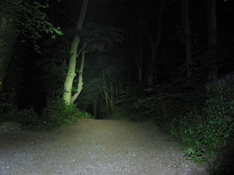 [/IMG]
[IMG] 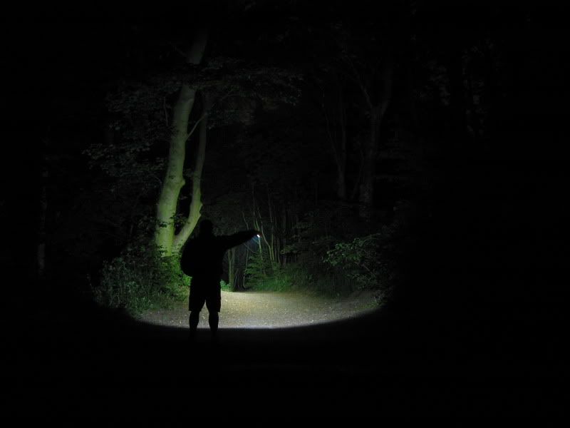 [/IMG]
Hmm... would be interested in trying this as a project as well. Could you take some photos while making it that will explain the more difficult things to a layman like myself?
OK will get all David bailley later today .
Ta, plus also, where on earth would I buy half the stuff on that list. I can find halfords, but LEDs on stars?
How is this one mounted as well?
(ive got a feeling you're going to wish you'd never started this 🙂 )
Why did I say HALFORDS when I meant to say
Maplins.
Will make it all clear and the bits realy are easy to get .
probably will regret starting it but may be fun for a few folks to have a go .
Trouty - how many lm is your daughter's light putting out - would it get swamped by a p7?
The cheapy P7 I tried had plenty of flood - but my bum right eye could use a bit more warning of approaching trees.
Still wondering if some Belladonna in my eyes and shades for the road may be my solution. 😉
Thanks
trout quick q not re this at all;
what's the chances/opportunities of doing a bluetooth/Radio remote for lights?
with a helmet light it makes sense (to me) to have a bar mount remote to control it rather than fiddling around on top of my head/on battery pack to find switch and adjust output.
I guess it would reduce the weight of head unit for helmet mounting if the remote controlled switch was mounted on the battery as well?
Stuey
No way would it get swamped by a P 7 more like show it up as a fraudster.
it is running at 960 ma drive so on paper lumens of 700 but as the Regina reflector is real good
it punches above it weight .
probably the best 20 mm dia optic for the XPG I have seen for throw
It is possible but beyond my experience some of the electronic geeks are talking about it but
I am of the KISS principle for my lights
ok, thanks
Just had a look on cutters and an XPG on a 20 mm star is £5.85
the Regina Optic is £1.79
and 2 of each is needed .
If anyone wants to give it a go then I have an order coming in from cutters soon via fedex .
and would be happy to add a few of these to it .
please dont mail me but register you want some on here and I will tot it up and add to my order.
and please dont swamp me with requests to add lots of other stuff as I dont have time to do the sorting out .
Trout,
Could you buy all the electrical parts and put them in a jiffy bag for home assembly. 🙂
Might as well build the bugger too 😛
and would have to add TAT on 😈
would this run off a 7.4 ni cad rc pack? i`ve got them!
quite up for doing this but an electrical numpty. what does the driver do and what does one look like?!
cheers,
Can I order the stars and optics please andrewgillies
AT mac DOT com am going to give it a go. How long do the batteries last BTW? Also do you know where I can get hold of a switch on a fly lead as I am looking to use this as a helmet light and would like the switch on the end of a wire cheers.
I have a P7 Airbike light which has failed, the battery is fine so was thinking about fitting 3 XPG's in the head unit, does anyone know if they would fit and if the driver would be sufficient (from memory I think its a 7.4V battery)?
Thanks
Doug
Van halen
it would just run but idealy need a few more volts and dont know if they would fit inside the case.
Driver here http://cgi.ebay.co.uk/ws/eBayISAPI.dll?ViewItem&item=260641549335
Some pics of the first bit done in dinner break
will explain when it is finished the fine detail.
http://s199.photobucket.com/albums/aa46/amticoman/DIY%20batteries%20inside/
Put me down for the star and optic bits please, im going to have a crack at this, Ta.
Do you have a link for teapot as I'm trying to find a driver but as I'm not sure could you point me in the right direction ta.
Lipseal
it's up there 2posts above. the bay link
Thanks thought that was for different batteries.
Hi Trout. This looks quite interesting. I'll await the report of the full build before adding to your order for LEDs (never tried anything like this before).
Was having a look on Maplin's website for the box. I assume its this [url= http://www.maplin.co.uk/Module.aspx?ModuleNo=33690#spec ]one[/url](although there are multiple models). From the dimensions i'm guessing the completed light will be 54 x 23 x 120. Would this be correct?
Anyone found a decent switch Ive been looking but can only find ip67 ones that are small enough on the RS web site(expensive 😯 )?
i'm just book marking this in care i get the chance to build one later in the year
is this any good ? [url= http://cpc.farnell.com/jsp/search/productdetail.jsp?sku=SW03135 ]IP67 switch not sure about current rating?[/url]
No we are looking for an on/of switch if only one light level
or three position switch if a low / hi and off is wanted.
a small toggle with a boot Would be OK
Lazy mike yes that is the correct box
might be able to cut it done a few MM in lenght
stueyI think the hole it needs is too big I've been looking around the 10mm mark, plus not sure if the led would work in the switch as batteries are only 7.4 v
Low and high for me, three toggle eh let the search begin.
Battery may be 15 volt Li Polymer smudge has some nice ones in stock .
but a 7.4 will do too but will dim a little as the voltage drops .
So need switch like this [url= http://uk.rs-online.com/web/search/searchBrowseAction.html?method=getProduct&R=1188246 ]3 toggle switch[/url]
Just checked the Airbike battery and its 3.7V so I guess that driver isn't going to work.
This is a single pole switch which is better...[url= http://uk.rs-online.com/web/search/searchBrowseAction.html?method=getProduct&R=1188218 ]RS again[/url]
I can't believe I'm spending my evening looking at switches!
I found this [url= http://www.kpsec.freeuk.com/components/switch.htm ]page[/url] quite useful for someone like me who doesn't know anything about electronics. I was looking on Maplin at switches and never realised how many different versions there could be (SPST, SPDT etc.)
I'm still confused about how the driver that is mentioned above works. It says it has a function for "half power". The picture on ebay shows 5 connections on the driver. I assume that the switch goes on the wiring between the battery and the driver. If you go for the switch lipseal mentions, I assume that you have two wires running from the switch to the driver. the other pole of the battery is connected direct to the driver. The 2 Connections (+ and -) to the LEDs (which are in series) make up the five connections.
Is that right? Sorry, this is all too much for a Monday night and its been a long time since high school physics!
troutie, could you please put me down for the leds and reflectors.
My email's in my profile.
thanks.
Maplin switch option but I assume not as good as the RS one.
[url= http://www.maplin.co.uk/Module.aspx?ModuleNo=2341 ]switch[/url] (Type B I think)
[url= http://www.maplin.co.uk/Module.aspx?ModuleNo=2348 ]Cover[/url]
Any thoughts?
Thats how I'm thinking Lazymike, now need the plug to charge it now.
Looking good on the switch front! 8)
Hi Trout,
Can you put me down for two reflectors and two leds.
email is in my profile.
ta very much.
Well I was about to order a new Magishine but really fancy having a bash at building one up myself.
What would the battery life be like on something like this and how would it compare to the Magicshine?
Another batch of pics gone in photobucket
http://s199.photobucket.com/albums/aa46/amticoman/DIY%20batteries%20inside/
/p>
its now working but waiting for glue to dry holding the Reflectors .
got 3 hours in it now and just got to cut a clear front and fit it and it is useable .
Got one of smudges 15 volt Lipo batteries in it 1 amp hour .
so I am thinking it should run for 2 hours on full well mine only has a full as used a switch I had in the used parts box
with 2 Xpgs running at nearly 1 amp it has 700 lumens and I am betting it throws a lot farther than a MS bastid .
I will charge it up tomorrow and run it down to check how long it will run
trout what glue is need am right in thinking high temp stuff, also did you use copper slip behind the led's?
Lipseal
I did use copper slip behind the leds and under the L where it mounts to the Box Its nearly as good as proper thermal paste .
I have used Arctic alumina epoxy to glue the driver to a bit of flat ali and then to the back of the cover plate.
It is possible with some thinking to shorten the box a tad .
I have taken off 12 mm but with hind sight and a bit more work I reckon it could lose another 12 mm but think twice before cutting
Trout - who is smudge for the battery link.
Not 100% connected but doing a few projects and access to paired lithium batteries and chargers always seem to thwart me.
Hi Trout could you email a wiring diagram plus any info for charging jack struggling a bit with that Ta
convert try this [url= http://www.mtbbatteries.co.uk/ ]smudge[/url]
Thats me Convert 😉
I'm just waiting for some information back from my suppler as regards the Li-Po Battery and then I should be able to fill you in on prices with or without a charger.
** Being a 1A Li-Polymer battery you wont be able to use the standard 4S Li-Ion Charger that you may of bought with a Troutlight or any other 15V Li-Ion Battery. The Charger will be a 0.5A as Li-Po cells are best charged at C/2 hence 0.5A **
Smudge = www.mtbbatteries.co.uk resident battery guru and nice helpfull guy
Here is it nearly done on the scales
[IMG]  [/IMG]
Hmm... this does look nice. However, also fairly challenging for a complete non-technical idiot such myself. Anyone around Hexham/Newcastle area up for doing a dual built with someone who has 2 left hands (basically you would make it and I would make tea...).
How mine is wired for one level
[IMG]  [/IMG]
OK this is a dead quick build report .
the only tools used for this build were
Hacksaw / files / electric drill / allen key / screwdriver / and stanley knife/ 3mm and 4 mm thread taps
I had some aluminium angle so that was used for the heatsink .cut to length to fit insde the hammond box .
care full positioning of the led stars and holes drilled and tapped but small bolts and nuts is as good if you have no taps
[IMG]  [/IMG]
as this is a cheap and cheerfull build I have used Copper grease as the thermal compound
but a small tupe of real thermal compound is not expensive
[IMG]  [/IMG]
[IMG]  [/IMG]
The Regina Reflector has 2 location pins but the led stars to match I could not find so the pins had to be cut off , Easy job and cleaned up with a file .
[IMG]  [/IMG]
You now need to get some holes drilled in the case to secure the leds and heat sink
this is where you need a little care for positioning and marking out of the holes
I did 2 x M3 and 1 x M4 all tapped the M4 is for a bar mount I have but may be better for a mount with 2 holes to stop it spinning round
I set the reninas level with the box edge
[IMG]  [/IMG]
[IMG]  [/IMG]
now a bit of soldering to add the pos and neg leads and connect the leds in series .
and put some insulating material under the screws to make sure they dont short on the solder pads
[IMG]  [/IMG]
A bit more copper slip on the base of the heat sink and assemble
[IMG]  [/IMG]
Battery I am using a 15 volt 1 amp hour Li PO pack from [url]www.mtbbatteries.co.uk[/url]
it came with 2 pos and 2 neg leads already wired to it and a small .5 amp charger .
[IMG]  [/IMG]
But you can fit in 1 double 18650 li ion pack also it will dim as the voltage drops and the driver goes out of regulation .
The battery went in next and is a perfect fit but some words of caution needed here .
this is a soft shelled battery and easily damaged which could be dangerous so be very carefull how you do this .
the rough edges of the hammond box needs filing smooth and I also put some dabs of silicon sealer around the battery to hold it in place .
[IMG]  [/IMG]
the little Teapot driver needs mounting and a small heat sink was cut from spare ali from the angle .
and glued to the driver . this also moved the solder pads up to stop shorting on the case .
[IMG]  [/IMG]
dont do what I nearly did and trim the wires too short which made it a begger to connect it all up .
simple job next to drill a couple of holes for the switch and charge socket .
[IMG]  [/IMG]
I have used a standard 2.5 jack and coated it with silicon in an attempt to keep water out
and will also get a rubber booted switch .
the driver and its heatsink / mount was then glued to the back plate and all wired up .
[IMG]  [/IMG]
I have gone for only one light level so here is my wiring diagram
[IMG] [/IMG]
check to see if it works
[IMG]  [/IMG]
and now a little fiddly job is to install the reflectors ..
they need glueing in and I used the trusty silicon round the base and when that is set will reinforce with small blobs at the top too stop them wobbling .
you need a steady hand here to get the leds in the centre and then just leave it to set .
[IMG]  [/IMG]
Last job when it has all cured is to use the remaining hammond end plate as a tempplate for a clear cover of some sort .
I have used some 1.5 mm polycarbonate for mine . sealed in with some silicon to keep the weather out .
[IMG] [/IMG]
defo count me in for some reflectors and LEDS.
ill try it with the batteries i have (as im skint from plumbing disasters) and save up for a proper one.
email markn at hop dot uk dot com
Had a mail from Smudge about the Li Poly battery seemingly they expand over time and need a little space in which to grow into .
and as they are a tight fit already not suitable for this project .
so it back to a Li Ion 2 cell pack for safety .though I will probably run this one now as it is built.
done a full to empty test also and it ran for 1 hour 41 minutes . this was on high only so it is worth using the dim mode too .
one word of warning dont wire the driver the wrong way round as it will die .
Im actually thinking now that if I go ahead with this, i'll essentially have spent a third of the price of a proper troutlite on something way inferior, and built by a hamfisted idiot. I think ill keep saving, thanks anyway Trout.
Very interested in this and feel that I should point out from the get go I know next to nothing about this kind of thing.
To increase the battery life could you use the same basic set up with an external battery pack and cut the hammond box down to make the head unit smaller?
Would this make it to hot and cook the innards?
What battery would you suggest using?
Stayhigh
Yes you certainly can and it has been done in the past see here for more information
http://forums.mtbr.com/showthread.php?t=407160
and you would get 2 lights from 1 box .
any battery from 9 volts to 20 volts is perfect for a double xpg build .
and that may happen to this light I have done if the battery dies
Not sure about light batteries but Li-Pos for RC cars (and aircraft) are pretty unstable and need proper balance chargers and careful storage to avoid a "lipo fire" (Youtube it if needed).
Noticed Four4th are using them for some of their batteries and the run times look good but they do state clearly that they must NOT be mounted on the bike so it's a rucksack only option - not entirely sure why but I guess there must be some risks involved?
I treat my RC lipos (one 7.4v, one 11.4 I think) with extreme care and charge them in a fireproof "lipo sack."
So do be careful!
Hi Troutie
Can I order 2 XPG's and 2 reflectors thesurfbus@yahoo.com
Thanks
Doug
Thanks for the link Trout, that'll keep me in reading for a while 🙂
I like the idea of having a bar/helmet set up so could you put me down for 4 LED's on star boards and 4 reflectors please?
jabbanawunga@hotmail.com
As far as batteries go what would give me around a 2-3 hour runtime?
OK so by my reckoning
Lipseal 2+2
Vinnyeh 2+2
steelfan 2+2
van halen 2+2
surfbus 2+2
Stay high 4+4
Order going in tonight when Australia wake up .
one of smudges 15 volt 2.6 ah Li ions would give an easy 4 hour on full plus a bit
and I think he has some 2.2 amp hour lots going a bit cheaper or did have .
tee hee. this is either going to be great or reside in the 'to do' drawer for a while.
i think the external battery option is for me. i wonder what i have in hte spares bin I can bodgee onto it for a bar mounted light?
oh and how would the dim mode wire up? do you wire a resistor in on that side of the switch? or is it more complicated?
Trout; after a quick scan of the mtbr thread you linked to, one of the builders uses 5 led's in one of his lights.
Would this be better then the two mentioned for this or would this be biting of more then I can chew so to speak?
Stayhigh that was before the XPGs IIRC .
better to keep it simple and with the 2 it really is a Bastid buster .
Van halen .
Teapot did 2 drivers one you needed to wire in a resistor for dimming and the other has a resistor built in and you need to switch in from control to negative to activate it .
I prefered the first one as with a 3 pos switch you could use the soft Off option whitch the built in one doesnt have .
Ok thats all good, I can do simple lol. I'll have to do one this month and one next, not much spare cash due to leaky bathroom roof 🙁
I'm going to use an external battery so will investigate making a battery pack possibly using 18650's(?) to strap under the bars.
Hi bit confussed now with the driver board, am I right in thinking that the other connection on the board shouldn't have a + but a - going to it or are you saying switch the - not the +? 😕
Trout, I've also been thinking about going down the external battery route. I have a 4 cell battery from a Hope LED2 which still has a reasonable capacity but the light itself is a bit weedy (i think its possibly 240lm). Would the 7.4V dim appreciably as it discharges?
I've had a look at typical discharge curves for Li-Ion and they don't seem all that flat. The Cree datasheet for the XPGs states a typical forward voltage of 3.3 V at one amp so two in series would be 6.6V. The info on the driver also states that supply voltage should be greater than 110% of the forward voltage. Based on that once the supply voltage drops to 7.26V the driver will start to have issues. Does anyone know what will actually happen to the driver once this happens?
Also, does anyone know what connectors Hope use and where to get hold of some. Would Smudge have some? I don't want to change the connector on the battery as the old head still works okay.
Finally, Trout, do you do conversions of old Hope LED2's? It might save me blowing myself up 🙂
Hi Troutie
Can I order 2 XPG's and 2 reflectors please?
Thanks
Simon
trout, personally i can understand the resistor bit so ill go with that. you lost me on the rest. ill contact teapot and go from there.
is resitor size relative to battery output? they are cheap so i guess i can just buy a few and see what works/happens
(this is like a GCSE physics lesson - i knew i should have paid attention in class)
cheers for the help!
Trout,
Stick me down for 2 XPG's and 2 reflectors.
Thanks,
Lyn
Lazymike are they 2.5mm connectors on the hope stuff, take it to Maplins and try a few plugs?
Bloody Hell CK you started this off and made history 😆
Will do and any tips on the thread would be appreciated .